6. Sampling Methods
T4su offers a four ways to sample your geometries. Sampling is very useful whenever a phenomena may be better studied with spatial discretization. whether they be flat surfaces or lines. They can be found by clicking Extensions > t4su > Edit :
6.1. Sampling the Bounding box
As with lines and geometries, the “ground floor” of your SketchUp can also be sampled into points or faces.
See also
Start by clicking Extensions > t4su > Edit > SampleBBoxArea.
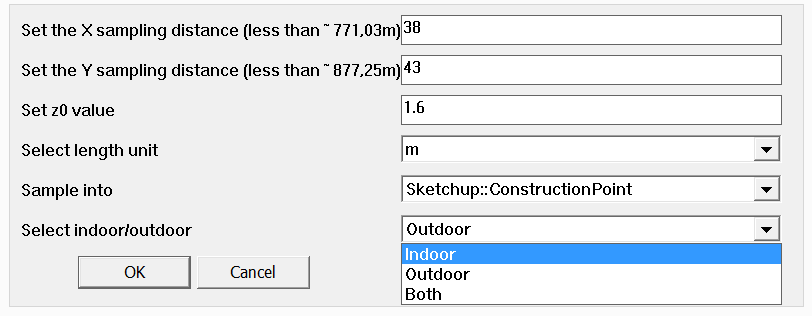
Sample BBox Command Box
- Set the X sampling distance : that is the direction of the red line in Sketchup. The “(less than [...m])” gives you an information on how large the bounding box will be.
- Set the Y sampling distance : that is the length of the sample in the direction of the green line.
- You can set the z0 value. You may want to change this for several reasons: if you are studying at which intersections a driver would be directly blinded by the incoming sunlight, it would be best to set the z-value at eye-level when sitting down. If you are looking at how much direct sunlight hits the ground, setting a z0 value to 0 or 0.1 is more appropriate.
- You can select your unit length, which should not change throughout your project, and be in concordance with your original SketchUp model.
- The “Sample into” is very important:
- If you select SketchUp::ConstructionPoint, points will be created. In this case, X and Y distances represent the distance between points (every Xmeters in the “red direction”, every Y meters in the “green direction”).
- If you select SketchUp::Face, rectangles or squares will be created. In this case, X and Y distances represent the length of the sides of the sampling area.
- Finally, selecting indoor or outdoor will sample either the area inside of your geometries (indoor) exclusively, or use the building faces as a limit to sample only the outside area (outdoor). If you choose both, the bounding box will be evenly discretized, ignoring any limits set by your buildings/geometries.
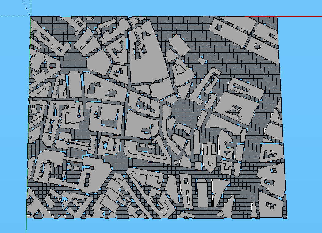
Up-facing view with sampling distances X and Y at 1m
6.2. Creating Point and Face Samples of your Buildings
As we have seen in previous posts, we can sample a line or your bounding box into points or faces.
We can perform the same type of task on your geometry faces. Here is how :
- Click Extensions > t4su > Edit > SampleFacesAreas
You will be asked to fill in the following command box:
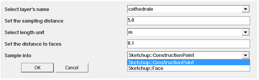
SampleFaces Command Box
- Select the layer to sample.
- Select the sampling distance : unlike SampleBBoxArea, you only have one sampling distance : you can only create squares, or points separated by an equal distance in both (X and Y) directions.
- Select your unit length
- You can also select the distance to face. Similar to the z0 value, the distance is calculated as the normal to the surface. Setting a small distance (eg:0.1) is helpful in avoiding pesky overlapping sketchup geometries.
- Again, you can choose to create points or faces. This really depends on what information you wish to visualize over the discretized space.
Here are two examples of the difference between Sample Points and Sample Faces, both with a 5.0m precision and 0,1m distance from the original geometries.
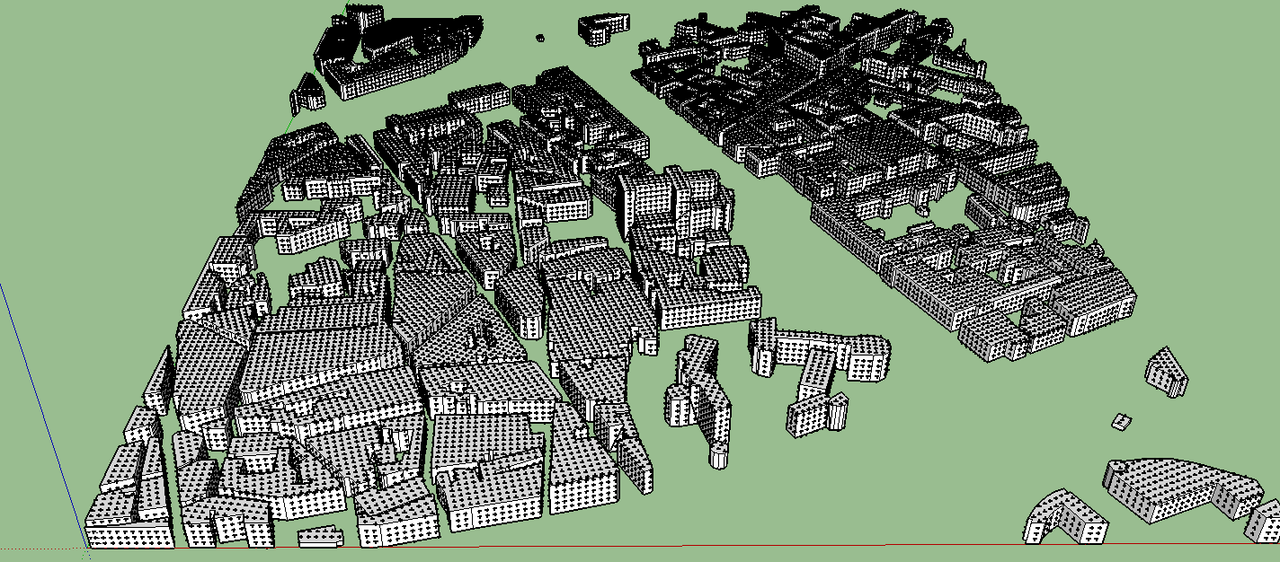
Result of Face Sampling
Result of Point Smapling
6.3. Sampling A Path
As We’ve seen, sampling methods will grid your your area of study evenly through point or line sampling, whethere they be your bounding box, or your geometry faces. You can also perform this operation on line segments : the command box for SamplePathway is comparatively very simple :
See also
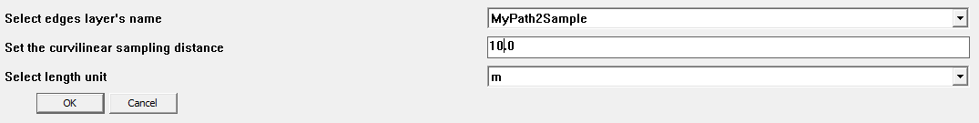
“SamplePathway” Command Box
- Select the layer containing your edge geometry.
- Set the sampling distance. Curvilinear is a fancy way to say we are leaving cartesian coordinates: the distance taken into account only follows the line segment, not the X/Y coordinates. If a line is 10m long and is sampled every 3m, three points will be made along the line at the 3m, 6m, and 9m marks.
- Always keep the same unit length throughout of your project.
You now have a new Layer called SamplePathWay_[original_file_name], containing points spread along your line.
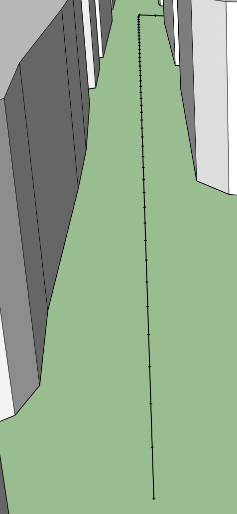
Line Segment Sampled every 5m.
6.4. Triangulating Geometries with Gmsh
Unlike other sampling methods which result in point samples, or quadrangular (square or rectangle) tessellations, Gmsh allows for a complete subdivision of your building geometries into triangles ; it creates smaller triangles where shapes are more variable, and larger ones on flatter surfaces.
See also
The first step of the process is to download Gmsh. Keep in mind where you decompress the .zip file ; you will need to copy/paste that location further on.

Next, click on Extensions > t4su > Edit > GmshTriangulator
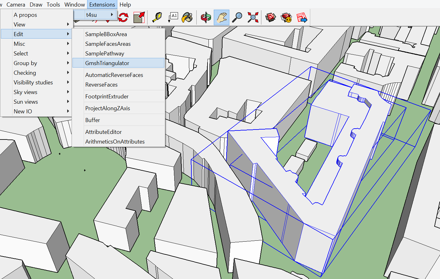
The command box that follows allows you to connect Sketchup to Gmsh :
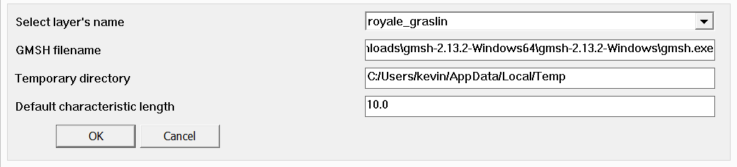
Gmsh Command Box (1)
- Select the correct layer. In this example, we’ve previously selected a building in our layer, the triangulation will therefore be performed only on that specific geometry. If nothing is selected, the triangulation will be operated over the entirety of the layer.
- In the text box below, paste the location of wherever you extracted the Gmsh zipfile, and add \gmsh.exe to the end.
- The triangulation will be saved in a temp file, you can decide upon its location in the third text box.
- Finally and most importantly, select the default size for your triangles, though some will be much smaller depending on the actual shape of your building. You may be tempted to create very small triangles for better precision, but keep in mind this will have a great impact on computation times, especially once you use them to analyse Sun View Factors for example.
The next window will tell you the number of triangles that were created. After clicking OK, A new window will appear that is very much like the one that appeared when you imported your geometry into Sketchup. Minimum and maximum x,y,z values express the recalibration of the coordinate system.
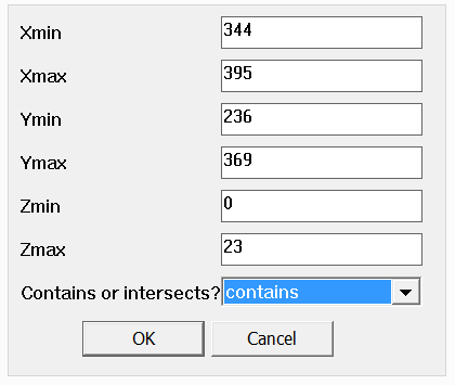
Gmsh Command Box (2)
Once you click OK, a new layer will be added, named as a series of numbers. Within it, you may find a copy of your original buildings whose faces have been triangulated.
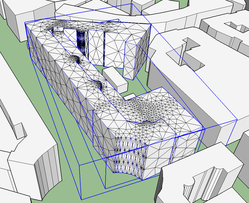
Building Triangulated with Gmsh.